|
|
|
![]()
New Laserhead LaCam 4HT
Fastest, most accurate, laser scanner for hot surfaces in the world


Due to echo digitization with full waveform analysis, measurements are less sensitive to smoke and dust influence. This leads to improved measuring results.

In the picture above each pulse represents an object that was detected by the laser. In the past the dust or smoke detected would have been used as the measured value. With echo digitization the actual brick refractory can be determined by finding the pulse with the farthest distance.
NEW FERROTRON SOFTWARE WITH ENHANCED 3D CAPABILITIES
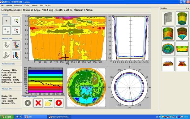
New software features
- all relevant information on one page
- any user action will show the requested data in all plots simultaneously
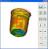
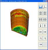
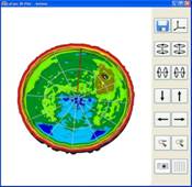
- powerful 3D graphics allows viewing the refractory lining from all perspectives
Typical Scope of Supply
Equipment: LaCam® M4 Profile Measurement System
Hardware:
Fastest, most accurate laser scanner available for hot surfaces.
Laser measuring system.
Industrial computer.
TFT 15.1” with IR-touch screen.
Water cooled laser head.
Class 1 laser product.
Software
Windows Operating System.
3D Evaluation Software (software is provided by license from Ferrotron
Measurement Software.
IRS/IPS – instant results scanning and instant positioning system software.
Change to standard customer generated reports included in service plan.
|
|
|